
Creating Custom Objects
Note: Before users can view custom objects, you must assign the corresponding object rights to their group. Each Custom Object has its own set of rights.
There are two approaches to creating a custom object: Copy an existing object definition, or create an object definition from scratch.
If the object to be created will have a definition similar to an existing object definition, you can copy the definition of the existing object, then modify the copy to reflect the exact properties you want in the new object definition. This may save time compared to creating the entire new object definition from scratch.
To create a custom object by copying an existing definition
- In the Designer, go to Object Definitions.
- Click on the existing object definition name.
- In the resulting page, click Create a Copy.
- A new page appears, showing general information for the new definition. You should immediately change the following field values:
- Name
- Name in Plural
- Unique Code (the present value is the same as the one from the existing definition, which would cause an error if not changed)
- Enter other appropriate general information in the fields as described in the General Tab on Custom Object Definition Screens table.
- Save the object definition.
To create a custom object from scratch
- To create a new custom object definition, select one of the following options:
- Click New in the Object Definition List screen.
- In the Designer window, click Create a new, and then select Object Definition.
- A new object definition screen appears with a blank General tab displayed by default.
- Enter the appropriate general information in the fields as described in the General Tab on Custom Object Definition Screens table.
- Save the object definition.
Continue defining object properties
Regardless of which approach you used to create the custom object, you should now continue defining its properties as explained in Customization Sequence.
Once the object properties match your solution design, the object is defined and displayed on the Object Definition List screen. For details, see Viewing Object Definitions.
Resulting User Interface and Other Changes
When you save the custom object information, the following events take place:
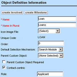
- You see the Create Involved and Create Milestone buttons at the top of the General tab.

- Two document folders with the object's name are automatically created in the Documents area and added to the following directories:
- Top Level/System/Object Definitions/Object Name
This folder stores all documents related to the design of the object definition, such as XML files for custom blocks, Involved and Milestone object definition files, document templates, and rules.
- Top Level/Attachments/Object Name
This folder stores all of the files that are uploaded to the object records.
Important: For each object record, this folder is created only when the record is saved and end users access the Documents block of that record for the first time.
- Top Level/System/Object Definitions/Object Name
For more details on document folders, see the Administration Guide.
For a complete overall procedure of defining custom objects, see Creating Custom Objects.
General Custom Object Information
The General tab of a custom object definition screen displays general information about the object as described in the General Tab on Custom Object Definition Screens table.
To add and save a custom object you must define its name in the singular and plural forms and specify its unique code. You may also specify the rest of the general information according to your design. For instructions on how to define a custom object, see Customization Sequence.
The following table describes the items on the General tab of custom object definitions.
General Tab on Custom Object Definition Screens
|
Item |
Description |
|---|---|
|
customObject Involved Party Milestone |
These hyperlinks provide access to the custom object's Involved and Milestone object definitions. They are only displayed once you define these objects. When you add a custom object, you cannot create Involved or Milestone objects for it until you save the custom object definition. When you save the custom object definition for the first time, you see the Create Involved and Create Milestone buttons (Create Involved and Create Milestone Buttons image). |
|
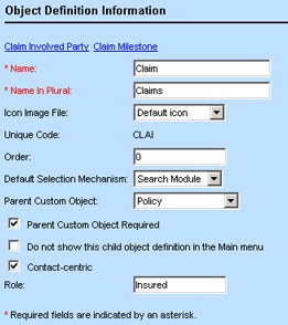
Name |
Type a name for the custom object. The maximum length is 50 alphanumeric characters. Important: The name must not start with a number and cannot contain special characters. This name appears in the end-user interface and names the corresponding Document area folder created for the object definition (see Resulting User Interface and Other Changes). Any special characters entered in this field are automatically converted to hyphens in Document area folder names. For example, Matter:Issue appears as Matter-Issue. |
|
Name in Plural |
Type the plural form of the custom object name. The maximum length is 50 alphanumeric characters. The plural name appears in the end-user interface where appropriate. |
|
Icon Image File |
Select the image file to appear in the following locations when users access records of this object:
You must upload all custom image files to the System>Icons folder at the Top Level level in the Documents area. Otherwise, the default image is used. All default images are generated from the class files and are not located in the Icons folder. For more details, see Default Object Icons. |
|
Unique Code |
Enter a four-character alphanumeric combination to uniquely identify this custom object. You can type the unique code in upper or lowercase. However, it is saved and displayed in uppercase. When you save the custom object, the unique code is always displayed as read-only and you cannot change it. The code must be unique for all objects, including Involved and Milestone objects, which are created from within custom objects. The unique code is used as the tree position for the root category of the custom object in the custom block XML files, XML layer, API rules, and Document Generator. |
|
Order |
Type an integer to specify where you want the name of this custom object to appear in ordered lists in the end-user interface. Each level in the parent-child hierarchies is sorted separately according to the order specified. The objects with the same display order are sorted alphabetically. |
|
Default Selection Mechanism |
Specify how the end user will select the object's records when they are referenced in other object records. For example, in the Parent field on the General tab of child projects, or in custom fields of type Custom Object. The available options include:
|
|
Parent Custom Object |
Select a custom object that must be set as a parent for the object you are defining. Important: This is not a mandatory selection, as it depends on your business model. For details, see Parent-Child Relations between Custom Objects. |
|
Parent Custom Object Required |
Select this check-box if having a parent custom object is mandatory for the custom object you are creating. |
|
Do not show this child object definition in the Main menu |
This field is available only for custom object definitions that require a parent. Select this check-box if you do not want users to create and access the records of this object from the drop-down lists in the end-user interface, or to avoid unnecessary clutter in the menus. This option does not affect user group rights to create or read these records. They can still do so from the respective parent records. |
|
Do not show New button in related object block |
Select this check-box if you want to hide the New button that provides a drop-down list of wizards in the related object block. For more information about the drop-down lists of wizards, see Testing and Troubleshooting Wizards. |
|
Contact-centric |
Select this check-box to make the object contact-centric. When you select this check-box, the Role field appears. Note: This setting is optional and should be based on your organization's needs. For details, see Contact-Centric Custom Objects. |
|
Role |
Enter the role of the contact on which the custom object is dependent. This becomes a field label on the General tab of all object records in the end-user interface. For details see Contact-Centric Custom Objects. This field appears only if the Contact-centric check-box is selected. |
|
Single Object Instance Only |
Select this check-box to specify that the custom object can have only one record in the end-user interface. When the user clicks the link for the custom object, TeamConnect automatically opens the only record. If the record does not exist, the user must create a record first. |
Creating Custom Objects
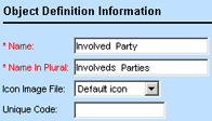
The Milestone and Involved custom objects are system objects that can be created and accessed only from within Custom Objects in Designer. For more information, see Unique Custom Object Types.
Whenever you add a new custom object, you see the Create Involved and Create Milestone buttons at the top of the General tab.
To create a Milestone or Involved object
- Open the General tab of the custom object definition where you want to create the appropriate object.
- Click either the Create Involved or Create Milestone button.
The corresponding object definition screen of the selected object appears with the General tab displayed by default. The Name and Name in Plural fields are automatically populated:
- (Optional) Type the desired name in the singular and plural for the object.
- (Optional) From the Icon Image File drop-down list, select the image file that appear when the user accesses the object records. Otherwise, the default image is used instead.
All image files are located in the Icons folder at the Top Level level in the Documents area. - In the Unique Code field, enter a four-character alphanumeric combination to uniquely identify this object.
This code is unique for each of these objects, regardless of the custom object it belongs to. - Save the object definition and continue defining its properties as described in Configuring System Objects.
- When finished defining the object's properties, save the definition and click the Refresh button at the top of the Object Definition page.
The Milestone or Involved object is defined.
Resulting user interface and Other Changes
When you save Involved or Milestone object information, the following actions take place for each object:
- The object's name appears as a hyperlink at the top of the General tab of the respective custom object.
- Two document folders with the object's name are automatically created in the Documents area and added to the following directories:
- Root/System/Object Definitions/customObjectName/milestoneName
or
Top Level/System/Object Definitions/customObjectName/involvedName
This is the folder where all documents related to the design of the object definition are stored, for example, XML files for custom blocks, appropriate object definition files, document templates, and rules. - Root/Attachment/customObjectName/recordUniqueID/MilestoneList
or
Top Level/Attachment/customObjectName/recordUniqueID/InvolvedList
This is the folder where all files uploaded to the object records are stored.
Important: For each Involved and Milestone record, this folder is created only when the record is saved and end users access the Documents block of that record for the first time.
- Root/System/Object Definitions/customObjectName/milestoneName
Milestone and Involved objects have the same set of object definition tabs as system objects and their object definitions can be customized like those of system objects. See Configuring System Objects.

The roles of the involved parties are defined through the Categories tab of the Involved object definition screen. See Using Categories.
Group rights to the Milestone and Involved objects are identical to those of their parent object. For example, if a group lacks access rights to the parent object, it cannot access that object's Milestone and Involved records. Likewise, search results for such records are not displayed.
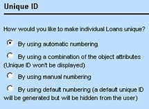
Unique Identifiers for Custom Object Records
Unique identifiers are unique combinations of alphanumeric characters assigned to each custom object record when it is created. Users can view unique IDs in the end-user interface if the identifier is set to be displayed.
You can assign unique identifiers for custom object records:
- By using auto numbering. See Creating Auto Numbering Patterns.
- By using object attributes. See Creating Unique Identifier Patterns from Object Attributes.
- By using default numbering
You can select the desired options for the project identifiers through the Unique ID tab of the respective custom object definition.
The following table explains each available option in detail.
Unique Identifier Options
|
Option |
Description |
|---|---|
|
By using automatic numbering |
Select this option to have TeamConnect automatically generate numbers for object records according to the specified pattern. When a new record is being created, the Number field will have the word Auto displayed in parentheses. When the record is saved, the Number field displays the assigned sequential number. See Creating Auto Numbering Patterns. |
|
By using a combination of the object attributes |
Select this option to create a pattern consisting of the object attributes that, taken together, will uniquely identify the individual object records of the selected custom object. No numbering will be displayed in the end user interface. See Creating Unique Identifier Patterns from Object Attributes. |
|
By using manual numbering |
Select this option to allow users to enter their record numbers manually. When a new record is being created, the Number field will be displayed as an empty text field where the user can enter the desired number. Tip: Remember to select the desired display format for the project hyperlink. See Project Link Display Format. |
|
By using default numbering |
Select this option to have primary keys automatically assigned to each project and stored in the database. No numbering will be displayed in the end-user interface. |
Depending on the option you choose at the top of the Unique ID tab, the bottom part of this screen may display an additional section where you can specify the desired properties.
Creating Auto Numbering Patterns
You can specify an automatic numbering pattern for generating individual record IDs for custom objects. A pattern can consist of a combination of the following elements:
- The date when the project is created
- A sequential number, which differentiates a particular project from the other projects created on the same day
- Any static information, such as a department name or special characters used as format separators
To set an auto numbering pattern for projects
- Open the Unique ID tab of the appropriate custom object definition.
- Select the By using automatic numbering option.
The Auto Numbering Pattern section appears at the bottom of the screen.
- Fill in the appropriate fields as described in the Auto Numbering Pattern Settings table.
- Select the format for displaying the project hyperlink.
- Click Save.
TeamConnect uses the new auto numbering pattern to assign a number to each new custom object record.
If you change the auto numbering pattern of an object definition, any existing records keep the previous unique identifier conventions until users update the records, at which point the new auto numbering pattern is used.
Updating the auto numbering pattern does not count as updating the object definition, so record locking is not enforced. However, updating other fields of the object definition causes an optimistic locking error.
The following table describes the auto numbering pattern settings.
Auto Numbering Pattern Settings
|
Field or control |
Description |
|---|---|
|
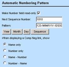
Make Number field read-only |
Select this check-box to make the project number uneditable. Important: If the number is editable, the user will have the ability to modify the number. These manual changes will take precedence over the automatic pattern. |
|
Next Sequence Number |
Enter a starting number for the sequential part of the auto numbering pattern. By default it is set to 0 or, if auto numbering has already been enabled, the next number in the sequence. |
|
Pattern |
Enter a pattern for the number, using any of the following elements:
|
|
Year |
With the cursor in the Pattern field, click this button to add a two- or four- digit year to the Pattern, for example, \Y\Y. |
|
Month |
With the cursor in the Pattern field, click this button to add a two-digit month to the Pattern, for example, \M\M. |
|
Day |
With the cursor in the Pattern field, click this button to add a two-digit day to the Pattern, for example, \D\D. |
|
Sequence |
With the cursor in the Pattern field, click this button to add a multi-digit sequential number to the Pattern, for example, \S\S\S\S\S\S\S. It is a good idea to base the number of digits that you include in the sequence on the number of records that are created in a day. For example, if your organization creates 100 claims per day, you might want to consider making the sequence consisting of three digits (\S\S\S). Important: You must include the sequence part into the Pattern, to make sure that the project number is unique. |
|
When displaying a CustomObject link, show |
Select the appropriate choice button to specify which format to use when displaying record hyperlinks of the object in other object records. See Project Link Display Format. |
Whenever a custom object record is referred to in other records or appears, for example, in search screens, it appears as a hyperlink. This hyperlink appears in one of the four available formats:
Project Link Display Options
|
Option |
Example |
|---|---|
|
Name Only (Default) |
Johnson v. Matthews |
|
Number Only |
2001-1018-003 |
|
Name - Number |
Johnson vs. Matthews-2001-1018-003 |
|
Number - Name |
2001-1018-Johnson vs. Matthews |
You may select the desired format on the Unique ID tab of the custom object for the automatic and manual numbering options. Existing records keep the previous settings only until a user makes changes or updates then. When a user updates an existing record, the new setting you specified takes effect.
Creating Unique Identifier Patterns from Object Attributes
You can specify a sequence of custom object attributes to uniquely identify individual custom object records. This can be useful to ensure that no duplicate records are created. For example, if you want to prevent duplicate matter records from being created for the same person involved in a dispute, you can create a unique identifier pattern that consists of the person's name, the type of dispute, and an incident date. In this way, you ensure that no two matter records with the same details are created for the same dispute.
For more information on attributes, see Using Object Navigator and Object Model: Read This First plus the additional reference tables this reference points you to.
To set a unique identifier pattern for projects
- Open the Unique ID tab of the appropriate custom object definition.
- Select the By using a combination of the object attributes option. The Object Attributes section appears.
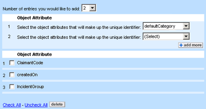
- Select the Number of entries you would like to add from the drop-down list.
- From each drop-down list, select the desired object attribute.
- If you want to add more attributes, click add more. Otherwise, click Save.
The object attribute pattern you defined for the custom object takes effect immediately. Existing records keep the previous unique identifier conventions until a user updates them.
Points To Remember
Keep the following points in mind when creating unique identifier patterns from object attributes:
- Object attribute patterns are stored in the database but they are not displayed in the end user interface.
- All object attributes you select for a pattern are added alphabetically one after another, no formatting is used.
- The attributes that you can select for the unique identifier patterns are automatically preselected by the system for you. They often include a few system fields, such as contact (applicable for contact-centric object definitions), name, nameUpper, defaultCategory, numberString, numberStringUpper, and all custom fields under the Root category.
- Even though taken in isolation certain attributes may never constitute a unique pattern (for example, name), taken together, they do.
- All object attributes you select for a pattern automatically become required fields for the end user.
- If you add custom fields to the pattern, remember to always include those fields in the custom pages you create.
Naming Patterns for Custom Object Records
Unlike unique identifiers, such as record numbers and object attribute patterns, that serve to uniquely identify each record in the database, names in custom object records are intended to provide a description of each record that may or may not be unique.
Depending on your organization's naming conventions, you can assign names to custom object records manually or automatically. Using an automatic naming pattern for project record names is useful when:
- Your organization has project naming conventions. For example, each dispute record must be named after the contact of the person or company that your organization is representing, the contact of the opposing party, and the type of dispute.
- Naming patterns can be identified in your organization's project names, even if there are no specific naming requirements or conventions.
- Spelling, or other errors and inconsistencies in record names may severely affect the business process.
You can set the record naming options for a custom object through the Name tab of its object definition.
The following table describes the naming options.
Project Naming Options
|
Option |
Description |
|---|---|
|
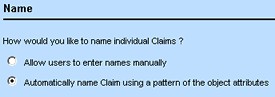
Allow users to enter names manually |
Select this option to have the user manually enter names for project records. When a new object record is being created, an editable Name field will be displayed for the user. |
|
Automatically name customObject using a pattern of the object attributes |
Select this option to define a naming pattern that will be automatically assigned to all custom object records. The name is automatically displayed as a read-only field after the project is saved. |
With the auto naming feature for custom object records, you can construct the desired pattern according to the standards and conventions accepted in your organization.
Example
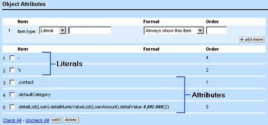
Consider an automatic naming pattern for a custom object called Loan where each record must be named after the contact who applied for the loan, the type of loan applied for, and the amount of money requested. The format for displaying this information would be: Applicant's LoanType - LoanAmount.
To create a pattern like this, do the following actions:
- The name of the applicant from one of the following elements:
- A custom field of type Involved that contains the applicant's name
- The contact attribute that contains the main contact's (applicant's) name, which is available only in contact-centric custom objects
By default, all persons' names appear in the following format: Last Name, First Name.
- The default category of the custom object that contains the loan type
- The custom field that contains the loan amount information
- The following literals:
- Apostrophe "s"
- Hyphen
- Three spaces between the attributes and literals
Tip: Whenever you have spaces around literals, add these spaces together with their literals, for example, a space after the 's, and two spaces before and after the hyphen. They are added even if you do not see them in the item list.
When you add the information to the name pattern of the custom object, TeamConnect automatically creates the name for each record when the user saves it. This way, all records are named correctly and consistently with your organization standards, based on the attributes you select.
Consider the following points when creating naming patterns for objects:
- The naming pattern of a record will reflect only those attributes that have values. If an attribute in a naming pattern has no value, it will not be displayed in the record name.
Tip: To ensure that all record names are properly displayed, you can make the attributes required. If you specify any custom fields, you must include them in your custom pages.
- Naming patterns must contain at least one attribute. They cannot consist only of literals.
- Project names support a maximum of 250 characters. If the data stored in the selected attributes and literals exceed 250 characters, the name of the project is truncated.
Tip: If you have added long strings to the naming pattern, consider abbreviating them.
- To have a person's name displayed in the naming pattern, specify a custom field of type Involved, or the contact attribute for contact-centric objects.
- By default, all person contacts' names will be displayed in the format Last Name, First Name. If you do not want to display the comma between the names or you want to change their order, you can use two attributes.
For example, instead of selecting the contact attribute for a contact-centric object, you have to add it twice and traverse further to select an attribute for each of the names:
contact.firstNamecontact.name
You may define naming patterns by selecting the Automatically name custom object using a pattern of the object attributes option button on the Name tab of the custom object definition. For instructions, see Creating Auto Naming Patterns.
Attributes are the building blocks of objects and contain the actual data you enter into TeamConnect. For example, you may use attributes in naming patterns for custom object records to ensure that certain values are consistently used.
Naming patterns can include such values as:
- Name of an involved party
- Specific dates
- Categories
- Names of other objects, such as parent objects or other custom objects
You can select the attributes you want to use in your naming patterns from the Object Attributes section of the Name tab of the custom object definition. Before you begin defining naming patterns for custom objects, you must have an understanding of how to use Object Navigator.
For more information, see Using Object Navigator and Object Model: Read This First plus the additional reference tables this reference points you to.
The following table describes the items in the Object Attributes section of the Name tab.
Object Attributes on Name Tab
|
Field |
Description |
|---|---|
|
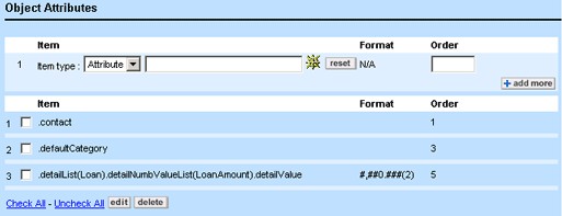
Item type |
Provides the following options:
Select Attribute to define attributes for the naming pattern. |
|
Object Navigator |
Click the Object Navigator |
|
Reset |
Click to clear the contents of the Item field. |
|
Format |
Select the appropriate format for the selected attribute. For different attribute types, different Format data entry fields appear. For more information, see Attribute Format Fields. |
|
Order |
Enter an integer to indicate the Order of the attributes selected. The integer reflects exactly where in the naming pattern you want the attribute to be displayed (beginning, end, or middle of the name). Items with the same display order are sorted and displayed alphabetically according to the first letter of the attribute selected from Object Navigator (for example, "c" in contact, not "S" in Smith). |
|
Item List |
Displays the object attributes (and literals) that are already selected to be used in the project name pattern. Select the check-box of the desired attribute and click either the edit or delete buttons. |

Depending on the type of attribute you select using Object Navigator, you can apply various display formatting options. For example, if you want the value of an attribute of type String to be displayed in upper or lowercase in each object record name, you select the appropriate format.
You can specify the following attribute format types in naming patterns:
- Boolean
- Date
- Number
- String
The following table describes the formatting options. For each of the object attribute types, two Format data entry fields appear.
Note: If you decide to select no formatting for the attributes, the default settings are used instead as indicated in the table.
Format Fields for Object Attributes on Name Tab
|
Attribute type |
Format option |
Description |
|---|---|---|
|
Boolean |
True value |
Enter true or false values in the appropriate data entry fields for Boolean values, which are most commonly displayed as check- boxes or choice buttons. For example, if "isRegistered" custom field is the selected Boolean attribute, you may want to enter "Yes" for the true value and "No" for the false value. Default Value: False. |
|
False value |
||
|
Date |
Pattern |
Select month, day, and year format for the date attribute. Default Format: The settings selected on the Preferences tab of the System Settings screen. |
|
Separator |
Select the symbol you would like to act as a separator between the month, day, and year of the date attribute. Default Format: The settings selected on the Preferences tab of the System Settings screen. |
|
|
Number |
Pattern |
Select the format for the number attribute. The display of the numbers is based on the locale. For example, in Europe the number 1.234,56 has a period (.) as a grouping symbol and a comma (,) as the decimal point. In the United States, the number 1,234.56 has a comma (,) as a grouping symbol and a period (.) as a decimal point. Default Format: The US standard, where the comma is a grouping symbol. |
|
Decimal Places |
Select the number of digits you would like to appear after the decimal point of the number attribute. Default Format: The settings at the time when the attribute value was saved in the database. |
|
|
String |
Case |
Select either UPPERCASE or lowercase to format the string attribute accordingly. Default Format: The settings at the time when the attribute value was saved in the database. |
|
Abbr |
If you want to abbreviate a string, select the desired abbreviation option. Whichever option you select, a blank data entry field appears for you to enter an integer. Depending on the option, the integer you enter specifies the following information:
Note: If an integer greater than the number of characters in the string is entered, all of the characters will be included in the abbreviation. |
Adding Literals
A literal is an alphanumeric or special character that is used as a separator between two attributes, or as a prefix or suffix to an attribute.
For example, if a user selected Smith, John as the applicant in a loan record, set Loan as the default category, and entered 20,000 as the loan amount, and the three attributes containing these values are added to the Loan naming pattern, the name of the project would be saved as Smith, JohnLoan20,000. Adding literals to the three attributes would create a clearer name for your users.
For example, you can add an apostrophe "s" with a space after it ('s ) as a literal after the contact attribute and a hyphen with two spaces around it. After adding these literals, the name of the project would be saved as Smith, John's Loan - 20,000. Otherwise, you can add a space as a separate character.
Important: A name cannot consist of literals only, it must have attributes.
You can select the literals you want to use in your naming patterns from the Object Attributes section of the Name tab of the custom object definition.
The following table describes the items in the Object Attributes section of the Name tab that you use to specify literals.
Literals and Object Attributes on Name Tab
|
Field |
Description |
|---|---|
|
Item type |
Select Literal to add a literal to the record naming pattern. |
|
Literal text field |
Enter the appropriate characters to create either a separator between two attributes, or a prefix or suffix for an attribute. Tip: To add spaces between literals and attributes, type the space together with the literal, for example, a space before and after a slash. To add a space between two attributes, you must add it as a separate literal called space character. |
|
Format |
Select the format for the literal by selecting one of the following options:
|
|
Order |
Enter an integer to indicate the display Order of the literals. The integer you enter reflects exactly where in the naming pattern you want the literal to be displayed (at the beginning or end of an attribute, or between two attributes). Items with the same display order are sorted and displayed alphabetically. |
| Item List |
Displays the object attributes and literals that are used in name pattern for projects. Select the check-box of the desired attribute or literal and click either the edit or delete buttons to make changes. |
To create an auto naming pattern for a custom object
- Review the Points To Remember.
- Open the Name tab of the appropriate custom object definition where you want to create a record naming pattern.
- Select the Automatically name custom object using a pattern of the object attributes option.
The Object Attributes section appears at the bottom of the screen. - Depending on your needs, do of the following actions:
- Specify the object Attributes whose values you want to appear in the object records' names, as described in the Object Attributes on Name Tab table.
- Specify the Literals that you want to add to the naming pattern of the custom object, as described in the Literals and object Attributes on Name Tab table.
Caution: If the data stored in the attributes and literals you select have a combined amount of over 250 characters, the name of the project is truncated, cutting off the information that appears after 250 characters.
- If you want to continue adding items, click add more. Otherwise, click Save on the toolbar.
The record naming pattern you defined for the custom object takes effect immediately. Existing records keep the previous naming conventions only until a user makes changes or updates an existing record. When a user updates an existing record, the new naming convention you specified takes effect.
When the naming pattern is set, the Name field in all records of the selected custom object appears as read-only.
Creating Phases in Custom Objects
All custom object records have their own life cycle consisting of a set of phases. The number of phases and their transitions varies depending on the custom object and your organization's business practices.
You may define the phases for a custom object on the Phases tab of its object definition and specify the transition from one phase to another on the Phase Transitions tab. For information about setting phase transitions, see Defining Phase Transitions for Custom Objects.
You may create and view all project phases for custom objects on the Phases tab. To access this tab, select Object Definitions from the Go to drop-down list, and then choose the appropriate custom object definition.
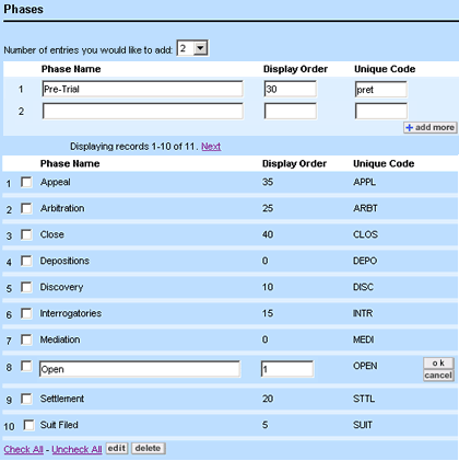
By default the Phases tab displays two phases, Open and Close. They are automatically set as the Initial and Final phases for the project life cycle on the Phase Transitions tab. You can always delete these two phases or rename them after you have added other phases.
|
Field or control |
Description |
|---|---|
|
Phase Name |
Type the name of the phase you are adding. The maximum length is 250 alphanumeric characters. This name will be displayed in two places in the end-user interface: the Phases tab and on the General tab (as the current phase) of the record. |
|
Order |
Enter an integer to indicate the order in which you want the name of this phase to be displayed in the drop-down lists on the Phase Transitions tab. The phases with the same Order are sorted alphabetically and displayed accordingly. Tip: It may be helpful to enter orders in increments of five. If you ever have to add more phases, you will have some leeway as to where in the drop- down list you can place the additional phases. |
|
Unique Code |
Type a 4-character alphanumeric combination to uniquely identify this phase. Note: You can type the unique code in uppercase or lowercase, however in the database, it is saved in uppercase. |
|
Phase List |
Displays a list of phases added to the selected custom object. Select or clear the corresponding check-boxes on the left to delete or edit the respective phases. |
Adding Phases
Before adding phases, write a complete list of phases you would like to add to a custom object. This helps you ensure that you add all necessary phases and facilitates the process of defining transitions between them.
To create a project phase for a custom object
- Open the Phases tab of the appropriate custom object definition.
- Select the Number of entries you would like to add from the drop-down list.
- For each data entry row, fill in the information as described in the Phases Tab table.
- If you want to continue adding phases, click add more. Otherwise, click Save on the toolbar.
- Define the desired phase transitions. See Defining Phase Transitions for Custom Objects.
Editing Phases
If you need to change either the name of a phase or its order, you can do so by editing the phase. However, if you need to change its tree position, you must delete the phase first.
Caution: If possible, phases should be deleted during the design stage when there are no existing records in the database. Otherwise, loss of data occurs.
To modify a project phase
- Open the Phases tab of the appropriate custom object definition.
- Select the check-boxes next to the names of the phases that you want to edit.
- Click edit.
The phase details that you can modify become editable.

- Make the necessary changes to the Phase Name or Order of the selected items.
- Click Save.
The changes you made become effective immediately upon saving.
Deleting Phases
If you need to delete a phase or change its tree position, you can do so by deleting the phase.
Caution: If possible during the design stage, try to delete phases while there are still no existing records in the database. If you delete a phase that is used by records, the phase information is permanently deleted from the records and the phase transition sequence is broken.
To delete a project phase
- Open the Phases tab of the appropriate custom object definition.
- Select the check-boxes next to the names of the phases that you want to delete.
- Click delete.
- When asked to confirm your action, click OK.
The phase information is deleted from the system.
Defining Phase Transitions for Custom Objects
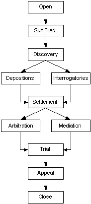
After you have created the phases necessary for the project life cycle of a custom object, you must specify the way these phases follow each other. Phases may branch into several alternative phases at the same level. For example, the following flowchart shows how the phases shown in the Phase Transitions Tab image may follow each other.
The process of creating a phase transition consists of:
- Naming the phase transition
- Specifying the phase from which the transition occurs
- Specifying the phase to which the transition occurs
- Determining whether the transition is visible to the end user
In the case of a linear transition, you specify the phases as you want them to follow each other, for example, from Open to Suit Filed and from Suit Filed to Discovery.
Even if you have only two phases, such as Open and Close, you must create a phase transition. In this case, select Open from the Initial Phase field and Close from the Final Phase field on the Phase Transitions tab.
When the phases branch, you must create multiple sequences, such as:
- From Discovery to Depositions
- From Discovery to Interrogatories
- From Depositions to Settlement
- From Interrogatories to Settlement
To access the Phase Transitions tab of a custom object definition, select Object Definitions from the Go to drop-down list, and then choose the appropriate custom object.
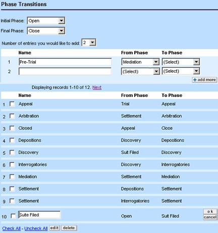
The following image shows the Phase Transitions tab of a custom object definition. Its phase transitions correspond to those shown in the diagram.
The following table describes the items on the Phase Transitions tab.
|
Field or control |
Description |
|---|---|
|
Initial Phase |
Select the phase you want the project life cycle to begin with. The Initial phase is automatically linked to the Opened On date field in the Project's General tab in the end-user interface. Note: By default, the Open phase is set as the Initial phase for all projects, and you can change it only when other phases are added on the Phases tab. |
|
Final Phase |
Select the phase you want the project life cycle to end with. The Final phase is automatically linked to the Closed On date field in the Project's General tab in the end-user interface. Note: By default, the Close phase is set as the Final phase for all projects, and you can change it only when other phases are added on the Phases tab. |
|
Name |
Type the name of the phase transition as you want it to be displayed for the end user in the (actions) drop-down list in the top right-hand corner of the of the Project screen. The maximum length is 250 alphanumeric characters. Tip: Type the name of the phase to which you want to go. |
|
From Phase |
Select the phase from which you want the transition to occur. |
|
To Phase |
Select the phase to which you want the transition to occur. |
|
Visible |
In this check-box, enter a check to make the transition visible to the end user, or clear the box to make the transition non-visible. Non-visible transitions are useful when the transition is always going to be accomplished through rule actions or other automated means, not through manual selection by an end user. By default, all phase transitions are visible. |
|
Phase Transition List |
Displays a list of phase transitions set for the selected custom object. Select or clear the corresponding check-boxes on the left to delete or edit the respective phase transitions. |
Creating Phase Transitions
Before creating phase transitions in TeamConnect, draw a diagram outlining the sequence in which you want the phases to follow each other. For an example, see Defining Phase Transitions for Custom Objects.
To create a project phase transition
- Make sure all the necessary phases for the project life cycle are created on the Phases tab of the custom object. See Creating Phases in Custom Objects.
- Open the Phase Transitions tab of the appropriate custom object definition.
- Select the appropriate initial and final phases from the corresponding drop-down lists as described in the Phase Transitions Tab table.
- Select the Number of entries you would like to add from the list.
- For each data entry row, fill in the information as described in the Phase Transitions Tab table.
- If you want to continue adding phase transitions, click add more. Otherwise, click Save on the toolbar.
The newly added phase transitions appear in the list of phase transitions and the available transitions appear in the actions drop-down list of object records. - Test the created phase transitions to ensure no infinite loops or broken sequences were created.
If the test is successful, the phase transition was successfully created.
Editing Phase Transitions
You can edit the name of a phase transition, but you cannot change its From and To phases. However, you can delete the transition and then recreate it.
Caution: If possible, phase transitions should be deleted during the design stage when there are no existing records in the database. Otherwise, data will be lost.
To modify a project phase transition
- Click the Phase Transitions tab of the appropriate custom object definition.
- Select the check-boxes next to the phase transition that you want to edit.
- Click edit.
The phase details that you can modify become editable.

- Make the necessary changes to the phase transition Name of the selected items.
- In the Visible check-box, enter a check to make the transition visible to the end user, or clear the box to make the transition non-visible. Non-visible transitions are useful when the transition is always going to be accomplished through rule actions or other automated means, not through manual selection by an end user.
- To change the Initial Phase or Final Phase, select the desired phase from the drop-down lists at the top of the screen.
- Click Save.
- Test the phase transitions to ensure no infinite loops or broken sequences exist.
Once the testing is complete, the phase transition is modified.
Deleting Phase Transitions
If you no longer need a phase transition, you can delete the phase.
Caution: If possible, delete phase transitions during the design stage when there are no existing records in the database. If you delete a phase transition that is used by existing records, the information is deleted from the records and the phase transition sequence is broken.
To delete a project phase transition
- Click the Phase Transitions tab of the appropriate custom object definition.
- Select the check-boxes next the phase transition that you want to delete.
- Click delete.
- When asked to confirm your action, click OK.
The phase transition information is deleted from the system. - Test the remaining phase transitions to ensure that no infinite loops or broken sequences exist.
The phase transition is deleted.
Defining Assignee Roles for Custom Objects
Assignee roles are job functions you define for users when they are assigned to a project in the end- user interface. Depending on the custom object, assignee roles may include, for example, associates, supervisors, adjusters for claims, defense attorneys, paralegals, and secretaries for legal matters. In the end-user interface, assignee roles appear in the Role drop-down list of the Assignees block of project record.
Assignee roles are lookup table items that pertain only to custom object definitions and are defined within them. They have tree positions that identify them in the database. For more details, see Using Categories and Lookup Tables. As a TeamConnect solution developer or administrator, you can insert the desired assignee role in the appropriate table or delete them if necessary through the Assignee Roles tab of the respective custom object definition.
Adding Assignee Roles
To add an assignee role to an object
- Open the Assignee Roles tab of the appropriate custom object definition.
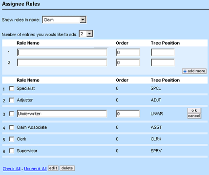
- In the Show roles in node drop-down list, select the desired hierarchy level where you want to add assignee roles.
- Select the Number of entries you would like to add from the list.
- For each data entry row, enter the appropriate information in the fields as described in the Assignee Roles Tab table.
- If you want to continue adding assignee roles, click add more. Otherwise, click Save on the toolbar.
The newly added roles appear in the list below the data entry fields and are immediately available in the end-user interface.
The following table describes the items on the Assignee Roles tab.
|
Field or control |
Description |
|---|---|
|
Show roles in node |
Select the desired node (hierarchy level), where you want to add assignee roles. |
|
Role Name |
Enter the desired unique name for the role. The maximum length is 50 alphanumeric characters. |
|
Order |
Enter an integer to indicate the order in which you want the name of this category to be displayed in the Role drop-down list in the end-user interface. Roles with the same Order are sorted alphabetically and displayed accordingly. Tip: It may be helpful to enter orders in increments of five. If you ever have to add more roles, you will have some leeway as to where in the drop-down list you can place the additional roles. |
|
Tree Position |
Enter a 4-character alphanumeric combination to identify the role. See Hierarchical Tree Structure for more details. Note: You can enter the tree position in uppercase or lowercase, however, in the database, the tree position is saved in uppercase. |
|
Role List |
Displays a list of roles created for the object. Select or clear the corresponding check-boxes on the left to delete or edit the respective roles. |
Editing Assignee Roles
If you need to change the order in which assignee roles appear in the drop-down list in the end-user interface, or their names, you can do so by editing these assignee roles. However, if you need to change their tree positions, you will need to delete the roles first.
Caution: Roles should be deleted during the design stage when there are no existing records in the database. Otherwise, data will be lost.
To modify an assignee role
- Open the Assignee Roles tab of the appropriate custom object definition.
- Select the appropriate node (hierarchy level) where you want to modify assignee roles.
- Select the check-boxes next to the assignee roles you would like to modify.
- Click edit.
The corresponding fields of the selected items become editable.

- Make the necessary changes to the Role Name or Order of the selected items.
- Click Save.
The assignee role is modified.
Deleting Assignee Roles
If, at the design stage when there are no existing records in the database, you need to delete an assignee role, or change its tree position, you can do so by deleting the assignee role.
Caution: If the roles you have selected are used in any records, the data entries in these fields will be deleted completely. Also, if you delete a node, all of its sub-levels and their data entries are deleted too.
To delete an assignee role
- Open the Assignee Role tab of the appropriate custom object definition.
- Select the appropriate node (hierarchy level) where you want to modify assignee roles.
- In the role list, select the check-box next to the item you want to delete.
- Click delete.
- When asked to confirm your action, click OK.
- Click Save.
The assignee role is deleted.
Customizing Notifications for Object Definitions
Notifications are sent by email to users who have opted to receive them whenever certain actions take place in TeamConnect. The default and custom system notifications can be replaced at the object level with custom notification templates. Customizing notification templates for an object definition as detailed below will supersede any custom notifications in the TeamConnect Admin Settings.
To customize a notification for an object definition
- Open the Notifications tab of the appropriate system or custom object definition.
- Select the desired notification template from the one of the following drop-down menu options:
- Set as an assignee—The notification that users receive when assigned to a record or task.
- Workflow approval request—The notification that users receive when assigned as the approver of a request.
- Workflow approval notice—The notification that users who complete an action that created an approval request receive when another user approves the request.
- Workflow rejection notice—The notification that users who complete an action that created an approval request receive when another user rejects the request.
- Workflow review request—The notification that users receive when assigned as a reviewer of a request.
- Workflow expiration notice—The notification that approvers receive to remind them that an approval request is about to expire.
- Workflow review completion notice—The notification that users receive when a review they requested is complete.
- Set as an attendee—The notification that users receive when added as an attendee to an appointment.
- Click Save.